confidential biji line drawing data format specification version 1.0, draft ------------------
Confidential
Biji Line Drawing
Data Format Specification
Version 1.0, Draft
------------------
Bijitec Pte Ltd © Oct 2001
1.
Handwriting Character and Hand-drawn Graphics
Biji Line Drawing is developed on Biji Technology, a system and method
for compressing stroke-based handwritten characters and line drawings
invented by Bijitec with a pending patent, to have a new type of
message format for handwritten characters and hand drawn graphics in a
message such like SMS, EMS or e-mail.
There are two types of Biji Line Drawing: Biji Character and Biji
Drawing. Biji Characters are line drawings that are treated as special
characters or symbols. It is displayed with the same height as normal
text. Biji Drawings usually takes up the whole output screen. Biji
Drawings can be used as hand drawn graphics, to convey
graphics-oriented information, e.g. road direction for a motorist.
Both Biji character and Biji Drawing are further divided into basic
and enhanced types. Basic character and drawing makes efficient
encoder and decoder possible on low-end devices while enhanced types
could have rich features like curve in character and attributes
(color, line width, shadow, fill information and simple animations
etc.) in drawings.
2.
Coordinate System
1.
Overview
Biji line drawing is vector based and scalable. Coordinate system used
in it is independent with what used for input and output. Two kinds of
coordinate systems are defined in Biji line drawing format, Global
Coordinate System and Local Coordinate System. The encoder selects one
of them to represent each element in drawings to achieve optimized
drawing quality and data size.
Both global and local coordinate systems in Biji line drawing are
limited in an area that we called “envelope”. In global coordinate
system, envelope is same as the drawing size. In local coordinate
system, an envelope is a square whose size in both directions equals
to half or one fourth the length of the height or the width of the
global envelope, whichever is shorter. Further more, local coordinate
system can be rotated by an angle over the global system. (note: it is
not a polar coordinate system).
As these coordinate systems are independent of actual input and output
coordinates, we define its origin and unit in following ways:
*
In global coordinate system, the origin is always at the left
bottom corner of the envelope. The envelope’s right top corner is
always defined as (1.0, 1.0). As width and height of the envelope
(drawing) are not same in many case, physical length of one unit
on x and y axis is not necessarily equal.
*
In local coordinate system, the origin can be at the center of the
envelope, or at the left bottom corner of it, similar to the case
of global coordinate system. For the latter case, coordinate unit
definition is also same, that is, the right top corner is always
(1.0, 1.0). While for the former case, as origin is at the center,
we define left bottom corner and right top corner of the envelope
as (-1.0, -1.0) and (1.0, 1.0) respectively.
To reduce data size of a drawing, both global and local coordinate
systems in Biji Line Drawing are defined by a grid and use integer to
represent coordinate values. The cross of the lines is called “grid
point”. Actual coordinates are snapped to the grid points when
described in Biji Line Drawing coordination systems. This may cause a
slight shift or displacement of points which are used to describe the
drawings. Each grid line is mapped to a value between 0.0 to 1.0. As a
result, we use only the “index value” as coordinate value for a point.
For example, if there are 5 “grid lines”, located at 0.2, 0.4, 0.6,
0.8 and 1.0 respectively, on a specific axis, we can use value 2 to
represent actual coordinate value 0.4. In other words, all points in
the drawing should be located at grid points in the envelope.
The number of “grid lines” or “grid points” in the global envelope
directly affects data size and drawing quality. For example, a
15x15-line grid needs only two 4-bit integers to represent all
“points”. In this 15x15 grid, the maximum displacement of points could
be up to 0.036 (1/28).. The fact is that, the more the number of grid
lines, the higher the resolution, and the better the drawing quality.
In Biji Line Drawings, the number of grid lines for both x and y axis
is defined as 2n-1 (map to value 0.0 and 1.0).
2.
Global Coordinates
Biji Line Drawing uses non-liner coordinate system as its global
coordinate system. This means the grid lines are not evenly
distributed over the envelope. Or in other words, the density of the
lines is not constant along the axes.
To describe a specific non-linear coordinate system, we use a curve to
represent “density” of the grid lines. “Density” is defined as
follows:
*
As a reference, we define density value 1.0 for a evenly
distributed grid
*
Density = 1 / (grid distance * (n-1)) where n is the number of
grid lines
*
Density can be represented as smooth curve when the number of grid
lines is large enough
Mathematically, the curve should have a total area of 1.0 above x-axis
in the diagram below. As a comparison, curve of the linear coordinate
system is a horizontal line with y value of 1.0.
In general, the density curve can be defined freely as long as it
covers an area of 1.0. I
n Biji Line Drawing, we simplify the curve description by restricting
the curve with the following parameters and conditions:
*
Number of peaks and valleys: a curve could have multiple peaks and
multiple valleys. Peaks and valleys are horizontal lines, which
are connected by a transformed Cosine curve.
*
Peak position: the central position of a peak
*
Peak density: a value equal or larger than 1.0
*
Peak width: a value less than 1.0
*
Transition width: width of a transformed Cosine curve connecting
peak and valley
*
All valleys should have the same density
These parameters can uniquely define a density curve. Once the above
parameters are determined, valley density, a value less than 1.0, can
be calculated.
Given a density curve, gird line positions can be calculated as
follows:
Vk =
Here Vk is the position of the kth grid line. n is total number of
grid lines. d(x) is the density function (or curve) we described in
this document.
To optimize different types of Biji Line Drawings, we preset the
density parameters.
For Biji characters, we have predefined some parameters so that only a
few parameters should be decided by the encoder.
Predefined parameters:
*
Number of peaks: 1
*
Peak width: 0.4
*
Transition width: 0.0
Variable parameters:
*
Peak density: 1.0 or 2.0
*
Number of grid lines: 7, 15, 31 or 63
*
Peak position: 0.2, 0.5, 0.8
For Biji drawings, we have following predefined parameters and
variable parameters.
Predefined parameters:
*
Number of peaks: 1
Variable parameters:
*
Peak density: 2.0 or 3.0
*
Number of grid lines: 7, 15, 31, 63 or 127
*
Peak position: 6 options from 0.0 to 1.0
*
Peak width: 4 options from 0.2 to 0.4
*
Transition width: 4 options from 0.0 to 0.3
3.
Local Coordinates
Local coordinate system, or local envelope is used for individual
elements [see definition in section 3.2] inside the drawing. When a
local envelope is used for an element, the element is described using
coordinates in the local envelope instead of the global envelope. In
one drawing, it is possible that multiple local envelopes are used.
Different from the global system, the local envelope is symmetric on x
and y axis and is a linear system that means grid lines are evenly
distributed along the axes. The grid in a local envelope is
independent to the grid used for the global envelope.
In Biji Line Drawing, local envelope is a square envelope whose height
and width equals to 1/2 or 1/4 of the width or the height of the
global envelope whichever is shorter. On the other hand, there are two
kinds of usage of local coordinate system: absolute mode and relative
mode.
Absolute Mode
For elements that can be fit into a local envelope, absolute mode is
used. In this case, all points in the element use a single local
envelope. In absolute mode, origin of the local coordinate system is
at left bottom corner of the envelope.
Relative Mode
For an element whose overall size is larger than a local envelope but
each of its segments can fit into a local envelope whose origin is the
center of the envelope and positioned at the starting point of the
segment, relative mode can be used. In this case, every segment has
its own local envelope. In relative mode, origin of the local
coordinate system is at center of the envelope.
When performing the encoding process, Biji Line Drawing Engine
intelligently chooses parameters for the global coordinates and
decides whether to use an kind of local envelopes to use for some
elements.
3.
Major Components
1.
Drawing Size and Aspect Ratio
As Biji line drawings are vector/stroke based and scalable, its size
is not defined in the format. However, it records an “aspect ratio”
for characters and drawings with different aspect ratio to maintain
same appearance for input and output. In order to render the drawing
to a bitmap representation, the pixel size of either the height or the
width should be provided to the decoder.
Aspect ratio for Biji characters are from 1:0.5 to 1:6 (height:width).
Aspect ratio for Biji drawings are 1:1, 4:3 and 16:9, all of which can
have portrait and landscape mode. More options are reserved for future
extension.
2.
Elements
There are four types of elements in Biji line drawings. Detailed
description are as follows.
Line
====
There are two types of lines: polyine and curveline. Definition of
them are as follows:
*
Polyline is a set of strait line connecting at least two nodes
*
C
urveline is a smooth curve connecting at least two nodes. Between
adjacent two nodes, curve shape is defined by a value called curve
offset -- the vertical (perpendicular) distance from the center of
the connecting strait line between two nodes to the curve.
Value of curve offset is independent with global and local coordinate
system. We use the ratio of base line length (strait line connecting
two adjacent nodes) to represent curve offset. It varies from – 0.5 to
0.5. Ratio value 0.5 or – 0.5 means that curve offset equals half of
length of the connecting line. In this case, the curve is close to a
half circle.
Shape
=====
There are up to 16 types of shaped defined in Biji line drawing. Every
shape needs a reference point to locate it in the global coordinate
system. The reference point should be located at the point that
indicate shape’s position. Shapes also have other necessary parameters
like rotation angle and size. Following shapes are defined in the
current version:
*
Dot
Reference point at center. No parameter.
*
Oval (including circle)
Reference point at center. Parameters include height, width and
rotation angle.
*
Rectangle (including square)
Reference point at center. Parameters include height, width and
rotation angle.
*
Rounded rectangle
Reference point at center. Parameters include height, width and
rotation angle.
*
Triangle
Three vertex at center of top and two lower corners. Reference point
at center of bottom. Parameters include height, width and rotation
angle.
*
Polygon
Reference point at center. A horizontal border should be located at
bottom of the polygon. Parameters include number of vertex, distance
from vertex to center and rotation angle.
*
Grid
Reference point at left top corner. Parameters include height, width,
number of rows and columns (up to 8).
Predefined Element
==================
In Biji drawing, a set of standard drawings can be used as its element
that we call predefined elements. Predefined elements can be Biji
drawing without attributes. They can also be in other drawing format
but should be identical to standard definition (see Annex 1). These
drawings should be stored in implementing devices. Predefined elements
have four major parameters: reference point, angle, width and height
and the reference point is at left top corner.
Following predefined elements are defined:
*
Arrow
*
Star
*
Heart
*
Flower
*
Smiley face
*
Crying face
*
Sun
*
Moon
There will be maximum 256 predefined elements.
Reused Element
==============
In Biji drawing, elements, in most cases lines, can be copied to
another place. The copied element is not necessarily to repeat its
data. Reused element is defined as a special element with only an
index to an existing element. Index value is just order in element
sequence in a drawing. Similar to predefined elements, reused element
should have position (point) and parameters such as angle, width and
height. Its reference point is at left top corner.
Both line and other elements can use global and local coordinate
system. There is a flag in data to indicate which coordinate system
should be used. It is determined by the encoder.
Implementation of latter four predefined element is up to implementing
devices. For example, radius of rounded rectangle and smiley face
appearance can have slight difference on different devices.
Basic Biji character supports only polyline while enhanced Biji
character supports both polyline and curve line. Biji drawing supports
all elements including predefined elements.
3.
Attributes
Enhanced Biji drawings could have following drawing attributes (global
attributes) and element attributes:
Drawing Attributes
==================
*
Background color: 64 color available (the only attribute)
Element Attributes
==================
*
Color: 64 color available
*
Line width: 4 levels
*
Line style: 4 types (solid, dash/dot, double, wave)
*
Block flag
*
Shadow flag
*
Blinking flag
Element attributes are applicable to line, shape and predefined
elements
Implementation of both drawing attributes and element attributes is up
to implementing devices. For example, line width and style can have
slight difference on different devices.
4.
Embedded Text
For Biji characters, it can carry a standard text string to represent
same content of the Biji character. Up to 256 (for ASCII) or 128 (for
Unicode or Asian languages) characters are allowed.
4.
Data Format
Biji line drawing data is a bit-stream. Practically, it is composed by
bytes. Bits in bit-stream and bits in bytes should have a correct
mapping rule, that is, higher order bits in bit-stream should be put
in higher bit in bytes. Unused bits in the last byte should be filled
with 0.
The format can be described in extended BNF notation as follows:
Biji Character
==============
; Coordinate parameters for x-axis and coordinate parameters for
y-axis
; Coordinate parameters for x-axis is present first in order.
; 0 for Biji character, 1 for enhanced Biji character,
; 2 for Biji drawing, 3 for enhanced Biji drawing
; Ratio (Height:width) = 1:0.5*(value+1). It is up to 11
; 0,1,2 is real length, 3 for an “extended length” embedded in content
; It decides number of grid points
; 0 for 7, 1 for 15, 2 for 31, 3 for 63
; 0 – peak density 1.0, no peak position required
; 1 – peak density 2.0, peak position 0.2
; 2 – peak density 2.0, peak position 0.5
; 3 – peak density 2.0, peak position 0.8
; Only present when
currently being used.’
; simple polyline is only applicable for Biji character
; while
[
< line type indicator > ::= ‘1-bit flag’
; 0 for polyline, 1 for curveline
< coordinate system indicator > ::= ‘integer (2 bits)’
; 0 : global coordinate system
; 1 : local coordinate system (large envelope)
; 2 : local coordinate system (small envelope)
; 3 : local coordinate system (use predecessor’s local coordinate
system)
; First node of the line is always at global coordinate system
; number of gird is always same as global coordinate system
; 0 for absolute mode, 1 for relative mode
; only present when use local coordinate system
; (
; n equals same bits used for x
; n equals same bits used for
; Curve offset (a ratio) r = e/L
; Here e is actual curve offset, L is distance between adjacent nodes
; We use an integer value to represent e. value = round(r*7) + 7;
; x and y coordinate
; n is decided by
; if
; if
; if
; if
; for local coordinates in relative mode, the highest bit is the sign
; indicator (1 for negative) and rest bits is a positive value
Biji Drawing
============
{ [
; only enhanced Biji drawing has
;
; Coordinate parameters for x-axis and coordinate parameters for
y-axis
; Global coordinate parameters for x-axis is present first in order
; 0 for Biji drawing, 1 for enhanced Biji drawing, 3 and 4 are
reserved
< display orientation > ::= ‘1 bit flag’
; 0 for landscape, 1 for portrait
; 0 for 1:1, 1 for 4:3, 2 for 16:9, 3 is reserved
; 0 for 15 levels, 1 for 31 levels, 2 for 63 levels, 3 is reserved
; Number of grid points.
; 0 for 15, 1 for 31, 2 for 63, 3 for 127
; It decides number of grid points
; 0 for 15, 1 for 31, 2 for 63, 3 for 127
; 0 for 2.0, 1 for 3.0
; 0-6. Peak position = value/6.
; 0-3, Peak width = value*0.05 + 0.2
; 0-3, Transition width = value*0.1
; only enhanced drawing supports shape, predefined element and reused
element
[
< line type indicator > ::= ‘1-bit flag’
; 0 for polyline, 1 for curveline
< coordinate system indicator > ::= ‘integer (2 bits)’
; 0 : global coordinate system
; 1 : local coordinate system (large envelope)
; 2 : local coordinate system (small envelope)
; 3 : local coordinate system (use predecessor’s local coordinate
system)
; First node of the line is always at global coordinate system
; 0 for absolute mode, 1 for relative mode
; n equals same bits used for x
; n equals same bits used for
; n is decided by
; Curve offset (a ratio) r = e/L
; Here e is actual curve offset, L is distance between adjacent nodes
; We use an integer value to represent e. v = round(r*k) + k;
; Here k = n**2-1
; 0 – 7 refers to dot, oval, rectangle, rounded rectangle, triangle,
polygon,
; grid. 8-15 are reserved.
; Optional parameters
; dot : none
; oval, rectangle, rounded rectangle, triangle:
; polygon and grid:
; 0 – 7 refers to arrow, star, heart, flower, smiley face, crying
face, sun and
; moon. 8-255 are reserved.
; x and y coordinate
; 0 – 31, representing 0 - 360 degrees. Real angle = value*11.25.
; n is decided by
;
; if < gird resolution>/
n = 4
; if < gird resolution>/
n = 5
; if < gird resolution>/
n = 6
; if
n = 7
; for local coordinates in relative mode, the highest bit is the sign
indicator
; (1 for negative), and rest bits is a positive value
; n is decided by
; n is decided by < local coordinate resolution >
; distance from center to vertex
; n is decided by
; number of vertex = value + 1
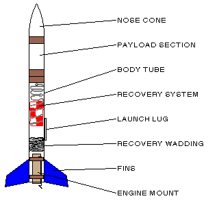 MODEL ROCKET DESIGN NOSE CONE USUALLY MADE OF BALSA
 SCREENING AND INTERVENTION FOR INTIMATE PARTNER ABUSE PRACTICES AND
 ENTERING GAME RESULTS VERSION HISTORY VERSION DATE UPDATED BY
 EXPRESIÓN ORAL “EL MOMENTO MÁS GRAVE DE LA VIDA”
 THIS FORM MUST BE SUBMITTED WITH THE IRB APPLICATION
 SIN CLASIFICAR DIRECCIÓN FORMULARIO DE SOLICITUD E INFORME PARA
 6 DOCAGA080502 PROPUESTA DE POSICIONAMIENTO DEL FORO EUROPEO DE
 NHS CORPORATE MEMBERSHIP OFFER AS AN EMPLOYEE OF THE
 ACUERDOS 2017 DE VIAJES EL CORTE INGLES PARA LA
 CHAPTER 41 ELEMENTARY PARTICLES AND THE BEGINNING OF THE
 ANNEX TO C SCIT 2505 PAGE 9 ANNEX TO